EazyCNC
EazyCNC is an application that runs on a personal computer and reads G-codes from a file translating them into motion control commands and sends the commands to a TOAD4 motion controller for realtime control of a three axis milling machine or plasma cutter.EazyCNC has been designed to be as simple and easy to use as possible so you should be able grasp the basic in a few minutes at one sitting.
However EazyCNC also supports a large sub set of G-codes as defined by the de-facto standard softwares for the hobby market EMC2 and Mach3.
Main View
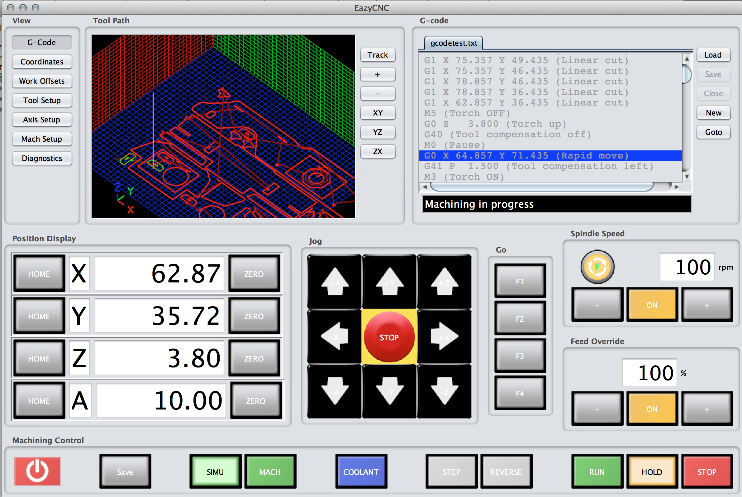
For a typical usage usage the main screen provides all the controls that are necessary to open a G-code file and machine the part it represents.On the upper right side of the corner the G-code file is shown with the blue highlighted line showing the current G-code line being executed.
On the upper left corner a 3D view of the tool path is shown with the path already executed shown in green and the path that remains to be machined shown in red.
Below those, from left to right, there are the coordinate read outs (DROs) displaying the tool position, jog controls to manually move the tool, user programmable function keys for repeated tasks and manual spindle controls and feed override controls.
At the bottom row there are buttons to control the actual machining and running of the G-code program, either in simulation mode or actually cutting some metal. With these controls it is also possible to temporarily pause the execution and run the G-code step by step and even backwards.
View Controls
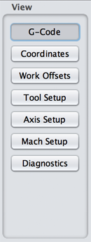
On the left on the upper half of the screen there are seven buttons that control what is show on the right upper half of the screen. The lower half of the screen always shows the controls that are used to cause the machine actually move.
The main view or screen that you typically need is the 'G-Code' screen that displays the tool path graphically and the G-code program text.
The other screens are for setting up coordinates systems, tool parameters and to configure various aspects of the machining system.
Simulation / Machining Controls
EazyCNC has a built in step level and accurate simulator to accurately predict and simulate the tool movements.
Simulation makes it possible to 'dry run' your G-code programs to verify correct operation and to avoid tool or machine damage and wasted material.
It is the modern equivalent of the old adage 'measure twice cut once'.
Of course it is also very handy for training and learning.
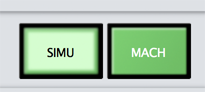
To turn on the simulation click the 'SIMU' button. In the simulation mode the system does not expect that the motor controller TOAD4 is connected so the simulation mode can be used without actual hardware or machine.
If your computer is fast enough the simulation will run in real time.
To actually start to operate the real machine click the 'MACH' button.
When the MACH button is 'on' EazyCNC sends commands to the TOAD4 motor controller so if you press the Jog or Home buttons or start the G-code execution with the 'RUN' button then the axes will move, the spindle will rotate and metal will be cut, so be careful!.
G-code Panel
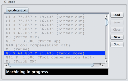 This panel shows the G-code that has been 'loaded' and indicates with a blue highlight the line being executed at the moment.
To load a new program simply click on the 'Load' button.
It is also possible to edit the loaded G-code program, for example to tweak some paramaters.
If you want you can also create a G-code program from scratch with the 'New' button.
Below the text of the G-code program there is a status line that displays messages to you indicating the current state of the machine.
Tool Path Panel
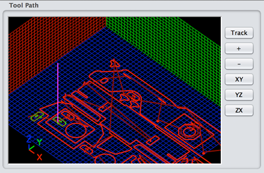 This panel shows a graphical 3D representation of the tool path generated by the currently loaded G-code program.
The tool path that has not yet been machined is shown in red and the path already traveled and machined is shown in green. The current tool position is shown in purple.
A light green or red line indicates that the spindle is OFF for those moves.
When the spindle is 'on' the tool path is displayed in a bright green or read and the width of the path matches the size of the selected tool showing the actual area cut by the tool.
The graphics is update in realtime as the machining progresses.
To zoom in or out click the '+' and '-' minus buttons or use your mouse wheel.
To move around drag the display with the mouse, to rotate the view hold the 'ALT' key down while dragging with the mouse.
Click the 'Track' button to cause the display to be automatically centered on the tool as it moves.
With'XY','YZ' and 'XZ' buttons it is also possible to get a 2D view of the tool path in the desired coordinate plane.
Digital Read Outs
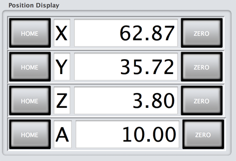
This panel shows the tool position.
The tool position is shown in the currently active coordinate system.
You can zero the display with the Zero buttons or change it by clicking the DRO and typing in a new value. This changes the coordinate system but does not move the tool. It does of course affect where the tool will move next when commanded to go to a certain coordinate position.
Typically you drive the tool 'manually' to a reference or zero position and click the 'Zero' buttons to indicate that this is where the coordinate system origin for you G-code program is.
The 'Home' buttons cause the selected axis motor to move towards the home / reference position / sensors / switch. Once the reference sensors actives the motor stops.
Jog Controls
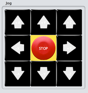
The arrow-buttons are used to manually move or jog the tool to the indicated direction.
The tool will first move slowly and then accelerate to the maximum speed for that axel as long as the button is held down.
When you release the button the motor will ramp down the speed and stop.
The red STOP button will stop all motor movements immediately, stop the G-code execution,clear all buffers and queues from pending movements commands and stops the spindle.
While this button is in effect a kind of emergency stop the system needs to have a real emergency stop installed that will cut off power to system, because this on-screen STOP button is implemented in software and relies on USB connection and cannot be relied to work in the presence of software bugs or system malfunction.
Pressing the STOP button stops the motors abruptly and thus it is likely that the stepper motors will 'loose' steps and thus the accuracy of the tool position and hence subsequent machining is off.
Machining Controls
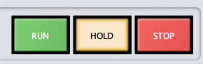
These buttons are used to control the actual machining and execution of the G-code program.
One of these buttons is always highlighted to indicate the state of the system.
To start or continue the machining press 'RUN', this will cause the EazyCNC program to start or continue reading the G-code program and translate it to motion commands and sending those commands to the motor controller.
Once you press the 'RUN' button the system will move the axes, start the spindle etc all by itself according to the setup and G-code information given, so ensure that everything is correctly and safely setup before you press 'RUN'.
Click the 'HOLD' button to temporarily pause the machining operation.
Pressing 'HOLD' will stop the axis movements as soon as possible but gracefully so that the it is possible to resume machining accurately.
The spindle will not stop if you pause the system with the 'HOLD' button nor will it turn back 'on' if you resume the machining with the 'RUN' button, you need to handle this manually.
In the hold state the jog controls can be used to move the tool position for example to be able to change a broken cutter. To resume machining click the 'RUN' button after which the tool will move back to the position where it was when the 'HOLD' button was clicked and the G-code processing will resume.
The 'STOP' button stops all the motions gracefully and stops the execution of the G-code program permanently.
If you start the machining with the 'RUN' button after pressing the 'STOP' button the G-code program execution will start from the beginning, rather than from where it was stopped or paused.
Step and Reverse Controls
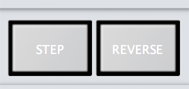
These buttons control how the G-code execution proceeds from line to line.
If the 'STEP' button is 'on' then a single line of G-code program is executed when you click the 'RUN' button, after which the system will automatically enter the 'HOLD' state.
This can be handy when you want to run the G-code program carefully and observe the effect of each step of the G-code program for learning or debugging your G-code programs.
If the 'REVERSE' button is 'on' then the G-code program proceeds backwards.
Running reverse does not really make sense because once something is cut there is nothing to cut anymore and the 'climbing' direction of the cutter is often critical and would be different if the movement is run backwards.
However, if a tool is broken in mid cut or you have a flame out in plasma cutter it is useful to pause the machining with the 'HOLD' button, change the tool, reverse and step one or two G-code lines and then resume machining in the forward direction.
Note that the 'REVERSE' and 'STEP' buttons do not cause any movement by them self, they just affect what happens when you the program moves to the next line. You still need to command the system to cut metal with the 'RUN' button.
If you turn 'on' the 'STEP' or 'REVERSE' while the system is in the 'run' state then the system will pause after the current G-code command/movement has been completed, it will not pause in the middle of a G0,G1,G2 or G3 movement.
Spindle Controls
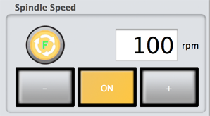
The Spindle Speed panel shows the current spindle speed and rotation direction.
You can also use it to manually control the spindle at any time.
To start or stop the spindle click the 'ON' button. The button is lit or 'on' when the spindle is running.
If you manually stop the spindle while a G-code program is running (the machine is in the RUN state as indicated by the highlighted or lit 'RUN' button), the spindle will automatically turn back on when EazyCNC encounters a G-code command to turn the spindle on. This can be dangerous, never touch the spindle or the plasma torch when there is the lightest change of the spindle turning unexpectedly on.
Always turn off power for the spindle/torch from the spindle/torch power supply before touching the spindle/torch!
To increase or decrease the speed click the '+' and '-' buttons.
To reverse the direction of the spindle click the round button that indicates the rotation direction with green 'F' for forwards and red 'R' for reverse.
Note that depending on your spindle set up running reverse or changing direction while running can be hazardous.
The real physical spindle speed is controlled by your Variable Frequency Driver (VFD) based on a signal from TOAD4, so the value displayed by EazyCNC is not the actual speed, rather it represent the signal sent to the spindle controller.
Feed Override Controls
The Feed Override panel can be used to tweak the feed speed. Feed speed is the the speed of movements of the axes with the G1,G2 and G3 G-codes and set by the the G-code F-word.
It may happen that the tool will start to chatter when machining and it maybe be necessary to increase or decrease the feed (as well as the spindle speed, see above) to improve the cut quality.
To do that click the '+' or '-' buttons to adjust the override in percentage of the speed set by the currently effective F-word in the G-code program.
Coolant Control
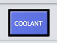
Coolant flow is typically controlled with the M7,M8 and M9 G-codes.
This button shows the current state of the cooling and it can be used to manually turn on or off the flow.
Like with the manual spindle control, turning the coolant on or off while the system is executing G-codes is permissible, but if the EazyCNC encounters a command to turn the coolant on or off the last command wins.
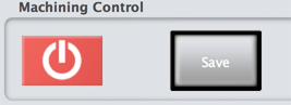
Quitting and Saving Machine State
EazyCNC contains hundreds of parameters and items of configuration information that you change via the views / screens screen described later.
Typically you do not change them all the time, but when you do change them you want the system to remember the settings for the next time. To store the settings permanently click the 'Save' button.
To quit the application click the red 'power' button. If you have made any changes to system configuration or parameter they will not be saved and no questions will be asked, so be sure to save important changes as soon as you make them.
Coordinates Screen
G-code supports a rather complex or flexible coordinate system, depending on your point of view.
This is mainly for historical reasons, G-code dates back to 1960's: in the old days it was important to be able to write G-code by hand because programs to generate CNC tool paths directly from CAD model or drawings where few and far between and not available in the machining shop. To make it easy to write numbers by hand various ways to 'simplify' coordinates were introduced.
Today is different, most industrial usage today uses a CAD program to generate more or less directly simple coordinate based G-code that has all the tool coordinate transformations and tool compensations already applied, all the CNC machine needs to do is to follow the coordinates.
This applies to hobby practice also, more or less.
Unless you really want to understand the coordinate systems you can mostly skip the information given here.
The only thing you need to understand ist that the coordinate readout displays (DROs) display coordinates in the same coordinate system as your G-code instruction uses. To define the coordinate system manually position tool to known coordinates and type in (or zero) the numbers into the DROs and as long as you have not turned on the tool compensation or or any other funny mode the tool will follow the coordinates in the G-code file, a G1 X100 Y200 will move the tool to until the displays show X=100, Y=200.
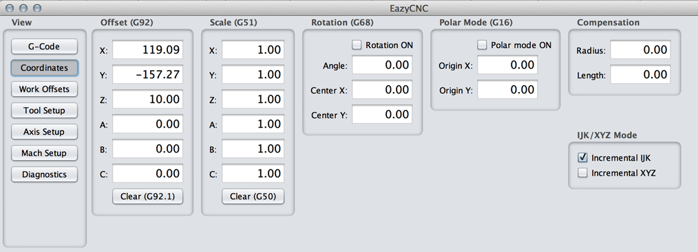
The Coordinates view shows and allows you to change (almost) all the parameters that affect coordinate systems.
When EazyCNC sees a 'pair' of coordinates in the G-code file it first applies scaling to the numbers. This scaling can be set with the G-code G51 and the current scaling can be seen and changed in the 'Scale (G51)' panel.
Next the G92 offsets are applied i.e. added to the scaled values. The G92 offsets can be seen and changed in the 'Offset (G92)' panel.
An other way to change the offsets is to type in numbers into the DROs or pressing the 'Zero' buttons; when you do that the software calculates and sets offset values that produce the desired display values for the current physical position of the tool without actually moving the tool.
After the offset has been applied the coordinates are rotated as specified in the 'Rotation (G68)' panel, if the rotation is enabled.
Next the tool length is added to the Z-coordinates, see below for 'Tool Setup' view.
Lastly the so called Work Offsets are added to the coordinates, see below for Work Offsets screen chapter.
Finally when the tool is actually moved the tool will be moved to the specified coordinates taking into consideration the tool radius explained below in the Tool Setup screen chapter.
It is also possible to use polar coordinates, handy in the old days for drilling holes on the circumference of a circle, not much used now days.
Because of some arcane reason it is also possible to use so called incremental XYZ and IJK modes of coordinate entry in which the coordinates are specified relative to the previous tool position.
The takeaway knowledge from this chapter is that you mostly never need anything else that the G92 offsets, which are simply values that are added to the coordinates in the G-code file to get the position the tool should be moved to (assuming of course that the you've not touched any of the other values show here, either through this screen or via G-code commands).
The idea of G92 offsets is that they allow you to position or move your tool path relative to the work piece. A negative offset moves your tool path in direction of the negative axis relative to the work piece. It is a bad idea to change any of the parameters here while machining is in progress, even if it is paused.
Work Offsets Screen
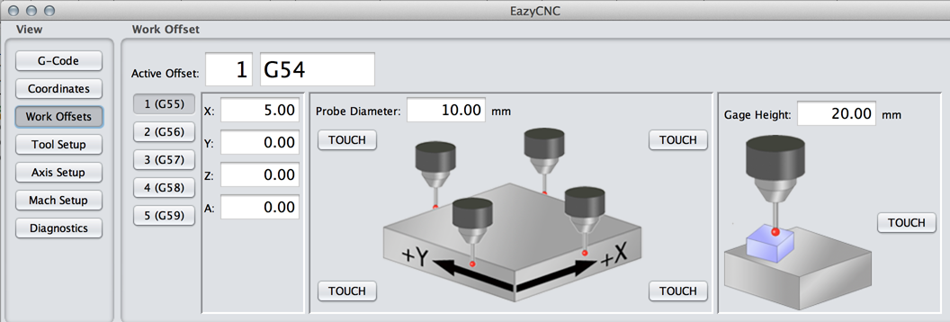
The idea of Work Offsets is that they allow you to repeat the same design or tool path multiple times on the same work piece at different positions i.e. produce a number of similar pieces from the same plank without resetting the coordinates.
EazyCNC supports 253 different work offsets.
The currently active set of offsets can be set via the G54 command or on this screen and the offset values for the active set are shown and can be changed here.
To set the offset value you can type in the numbers into the appropriate entry fields or you can use the 'Touch' feature.
To use the 'Touche' feature for X and Y you move the tool with the Jog Controls so that it touches the appropriate edge of the workpiece, type in the tool diameter and click the appropriate 'Touch' button; this will calculate and set the appropriate work offsets for the active Work Offset set.
Similar procedure is used for setting the Z-offset but there you typically use a gage or feeler piece between the tool and work piece and hence you type in the gage height in the appropriate entry field. Note that if you are using the Tool height compensation (see below Tool Setup view) you should first set up the tool height correctly before 'touching' to set the Z offset.
Tool Setup Screen
EazyCNC can store the diameter and length of 253 tools or cutters and compensate for them automatically.Tool radius compensation means that the tool path is automatically modified so that the tool cuts outside of and leaves un-cut the desired outline even though the G-code describes only the desired outline of the finalized work piece shape; without the compensation the work piece would be cut too small by the tool diameter.
Tool height compensation means that the Z-coordinate system is automatically adjusted to take into account the length of the active tool.
Tool length compensation requires a tool holder system that allows you to consistently and repeatably change tools without loosing the tool registration. Because of this (or lack of it) hobby set ups typically don't use the length compensation.
Tool radius compensation however is very useful in hobby context as many programs exist that can trivially turn a CAD drawing into an uncompensated path in G-code format. It is also easy to write simple BASIC or Python code to generate G-code for specialized applications and in that context automatic radius compensation done at the machining stage is very useful.
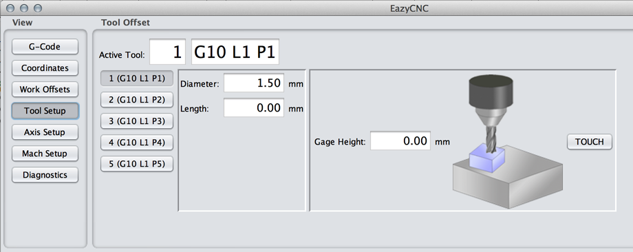
This screen shows the active tool number and the tool diameter and length of the active tool.
You can change the active tool by executing appropriate G-code instructions, typing in a tool number or you can use one of the buttons in this screen.
To setup the active tool's length and offset you can type in the numbers into the appropriate entry fields or you can use the 'Touch' feature.
To use the touch feature you use the Jog Control to drive the tool so that it touches the top of the work piece, typically with a feeler or gage piece in-between. Then you type in the gage height into the entry field and click 'Touch'.
Axis Setup Screen
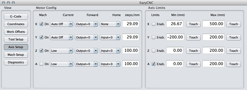
The Motor Config panel is used to tell EazyCNC how it should control the TOAD4 motor controller to get the desired movements.
For each motor/axis there are four parameters, drive current, forward direction output polarity, home or reference switch polarity and the steps/movement ratio.
steps/unit
Depending on the units (mm or inch) selected for the machine this parameter specifies the number of stepper-motor steps required to move one mm or inch.
For example if you are driving a lead screw with 3 mm/revolution pitch directly from a typical stepper motor with 200 steps/revolution then your steps/unit is 200/3 or 66.666 steps/mm.
The numbers of decimal places shown for the 'steps/unit' depends on the selected number of display digits but you can enter as many decimals as you need and they will be stored accurately up to 16 significant digits.
If you change the 'units' for the system you do not need to re-set this value as it is stored in internal units and just converted to the display units as required, for example if you change to the use of inches the 66.66 becomes automatically 1693.32 steps/inch.
Current
The TOAD4 supports driving the stepper motor at two currents that are selectable via jumpers on the TOAD4 board for each motor individually.
These are called, logically enough, 'High' and 'Low'. In addition to those there are two other options 'Auto Hold' and 'Auto Off'.
With High or Low selected the motor current for that axis will always be high or low, regardless of if that motor is running or not.
With the Auto options when the axis is in use the high current is used and a short time after the motor stops the current is automatically set to low or turned off completely.
Typically you select/set the high current via the jumpers to be as high as your motors can stand and you want to run motors at that current to get the best possible acceleration without loosing any steps.
Also typically the motors will get hot at the High current so when the motors are not in use you would like to use a lower current i.e. the Low setting but you also do not want to turn the current totally off because this may cause the motor to become so 'relaxed' that the axis may move on its own accord and loose accuracy.
In other words you typically set the current to 'Auto Hold' which means that the axis is run at high current but when it is not moving the current set to the low or hold value.
Forward Output Polarity
A single output for each axis on the TOAD4 board controls the step direction.This setting determines weather that output is logical 0 or 1 when the axis moves forward i.e. towards the positive or increasing coordinates.
Home or Reference Input Polarity
A single input on the TOAD4 board controls is provided for the home aka reference switch for each axis.This setting determines weather that input is a logical 0 or 1 when that axis motor / mechanism is at the home or reference position.
Home or reference position is a position selected by you and passing of which will change activate or deactivate the reference switch.
The reference switch must be so arranged that when the axis movement mechanism is on one side of the reference position the signal is a logical 1 and when the mechanism is on the other side the signal is 0. It should not be possible to move the mechanism 'over' the switch so that the signal is the same on both sides of the home position.
The home or reference position is typically chosen so that it is always safe to drive to that position regardless of the tool in the holder. Also the time it takes to 'home' the motors is something to consider.
That is why the X-axis home position is often in the middle where it is typically safe and fast to drive because most often the XY table works near in the middle positon.
Y axis home position is at back or front depending on weather it is the table or the turret that moves; the Y axis is typically a shorter movement than X movement so speed is not a big issue and it is handy if home position gives good access to the the work piece.
Z axis home position is typically at top position because this lifts the tool from the work piece instead of ramming it in when homing.
To set the correct polarity for Forward Output manually Jog the axis in question. Pressing the '+' Jog for an axis should move the mechanism to towards the positive or increasing coordinate direction. Typically the positive directions are towards right,back and up when the machine is viewed from the front, assuming that we are talking about a machine where the tool moves. If you have a machine where the table moves then the directions are reversed.
If the axis moves in the wrong direction just change the Forward settings.
To set the correct polarity for the Home Input manually Jog the axis in question to a position where the home / reference switch just becomes activated and press the 'Home' button for that axis.
If everything is correct the axis motor will run shortly and slowly crawl out of the home position in the 'positive' direction and stop.
If the motor instead first moves one way until the reference switch changes state and then the other way then either the polarity was wrong and you need to try the other polarity for the Home input or the mechanism was not at the home position.
It is also possible to set the Home switch polarity to None to indicate that no home switch is used, which again is very typical in a hobby context.
Axis Jog Limits
The Limits panel is used to tell EazyCNC if and how it should limit the axis movements.The axis limits only apply to the manual Jogging, not G-code movements. You should visually check that the G-code tool path will not override the limits and crash the machine.
The axis limits are graphically displayed as a colored grid on the tool path display.
The axis limits are based on and tied to a coordinate system where the zero position is defined by the limit switch position. The G-code coordinate systems, offsets and DRO values have no fixed relationship to the movement limits.
If the limits are enabled then the system will not allow you to jog beyond those limits. For that to work it is necessary for the system to 'find' the Home position.
If the Home / Reference switch input is enabled (ie it is not set to None in the Motor Config panel) then pressing the Home switch for that axis will find the reference position and set internal coordinate system for the limits.
If the on the other hand home / reference switch input is not enabled then pressing the Home button will designate the current physical tool position as the zero position for that axis.
If you are using this option (limits without reference switch) then you need to manually Jog the system to the 'zero' position and press the Home button. And you need to do this every time when you restart the system before you do anything .
Note that while you are in this Axis Setup view the Jog limits are not enforced because otherwise you could not Jog as necessary.
To set the limits you can type in coordinates if you can figure them out or simply Jog to the appropriate physical limit (or preferable safely close to it) and press the corresponding Touch button.
Machine Setup Screen
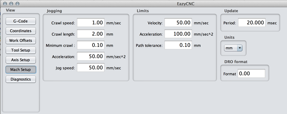
This screen allows you to set up general parameters related to all machining operatios and movements.
The Jogging panel allows you to set the crawl speed, length and a minimum length. Crawl refers to the slow initial speed when you press the Jog button, the axis will first move at crawl speed until it has moved the specified distance. If you release the button before that the crawling will still continue until the minimum distance has been traveled.
The Acceleration and Jog speed define how fast and to what speed the axis speeds will ramp up if the jog button is held down.
The Limits panel defines absolute limits for the movements.
The Acceleration defines how fast it is safe to accelerate or decelerate the movements under any conditions. This depends on the mechanics, electronics and motors used and needs to be experimentally found out. You want to use as fast acceleration as possible but with a safety margin so that you will never loose steps.
To test this you should construct a G-code test sequence that will do a series of back and forth rapid G0 movements and run that with different accelerations. After each test you need to verify that the tool returned to exactly the original position, otherwise steps were lost.
The acceleration test needs to be verified separately for each axis.
Obtaining maximum acceleration is important in plasma cutting as slow acceleration reduces the attainable cut speed which in turn has effect on how thin metal you can cut and the width of the cut.
The Velocity parameter defines the maximum or rapid movement speed that is used when a G0 command is encountered. For the normal machining movements G1,G2 and G3 the speed defined by the F-word is used.
Path tolerance defines how closely EazyCNC tries to follow the path specified by the G-codes program. A tolerance of zero will cause the path to be followed exactly but will also cause the feed speed to reach zero or come to stand still at corners, where as a big tolerance allows the tool to take corners at speed. For plasma cutting it is especially important not to stop at any time when the torch is on.
The Update Period parameter defines how often EazyCNC will update new postion to the TOAD4 motor controller. A too slow update will result in the tool path only being updated at long distances and a too small value will choke your computer because it can't keep up with the requirement.
A typical good value is 20 msec as this means that even at a fast plasma cutting speed of 4800 mm/min or 80 mm/sec the path will be update at least every 1.6 mm, which is still acceptable given the accuracy of a plasma arc.
The Unit panel allows you to use eiher mm or inches in the system. You can change this at any time, it will only affect the values displayed in the various screens but will not affect any movements. The units used in G-code are defined by the G20 (inch) and G21 (mm) codes.
The DRO format panel allows you to define how many digits you want to be displayed for the values in the screens. To display three decimal digits set the format to '0.000'.