
[ TOAD4 MANCTL ] 9.8.2020
TOAD4 Manual Control Panel
Some time ago I realised that some people might like to use their CNC milling machine as a manual mill.
This is fine but it requires a few things from the setup:
The first one is obvious of course but the second one depends on the electronics, specifically the stepper drivers. TOAD4 board stepper drivers (TB6560) allow freewheeling when the enable signal is not active.
The enable signal is only active if the TOAD4 board is powered up and the EazyCNC software is running in the MACH mode, so you are good to go if you do not power up the TOAD4 board or run the EazyCNC software(1).
If you are NOT using the TOAD4 board, then it really depends on the actual stepper driver module if you can manually turn the axis or not.
The TOAD4 LPT board does not output any enable signal to the LPT for because the targeted stepper driver G540 does not take in any. So it really depends on if the driver module you are using allows free moment when not powered up. While I do have a G540 setup my mill has no handwheels so I cannot reliably assess if that is the case.
But the third bullet above is really the subject of this page, how to control the spindle and coolant manually in the CNC setup.
The problem
Because the spindle and coolant are wired to the TOAD4 electronics you would have to fire up the computer, wait for it to boot and start EazyCNC to manually control the spindle with the on-screen buttons. That is both slow and cumbersome because the computer screen is likely not very near to the milling machine to prevent coolant and chips flooding the computer.To solve that dilemma my trusted pilot user Erik has wired his setup so that he has a big double throw multi pole switch that switches the spindle and coolant signals between the TOAD4 signals and manual front panel switches. And this works fine but it requires a LOT of wiring. Especially if you were to do this with standard TOAD4 board (which Erik does not use) it would require a nine pole two throw switch with 27 wires!
Inconvenint and expensive. Outch!
When an other user wanted to duplicate that he got me thinking that there has to be a better way.
The obvious solution would be to connect the front manual control switches directly to the TOAD4 board and modify the firmware so that it can take its commands either from the computer or those front panel switches.
Unfortunately there is not enough free IO on the TOAD4 board and while the board could be modified that would not help people who already have board, not to mention making the board more complicated and expensive for everyone although only some people would need the manual control feature.
After a lot of head scratching a solution was found.
The TOAD4 Manual Control Board
By creating an extension board with a tiny cheap PIC processor and utilizing the analog POTENTIOMETER INPUT on the TOAD4 board as a digital serial communication channel I was able to conveniently expand the IO to accommondate four switches and a potentiometer for speed control.
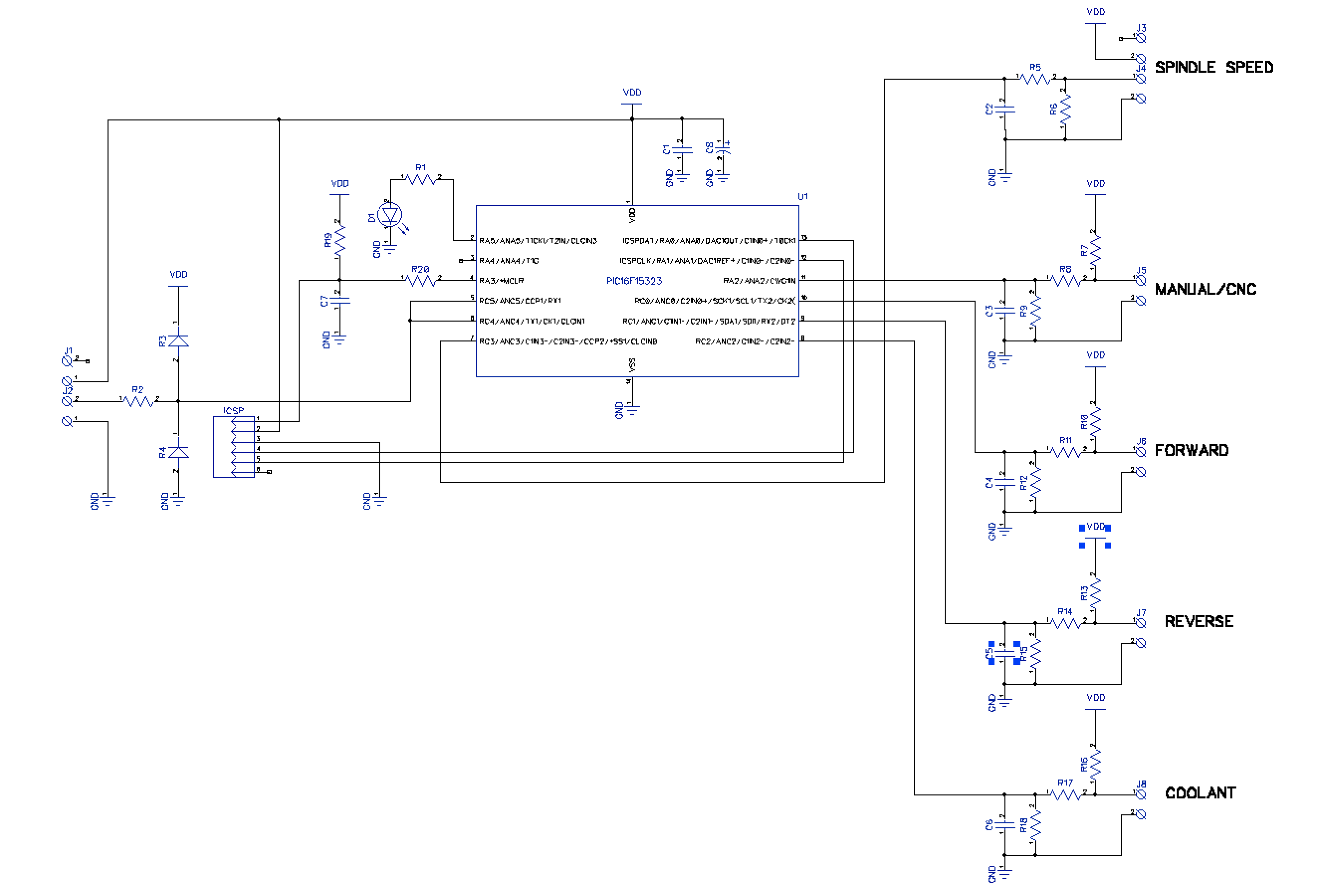
The TOAD4 Manual Milling Extension Board Schematics
To be able use this with TOAD4 only requires a simple modification to the TOAD4 board, namely soldering a resistor parallel to one already on the board.
Bill of materials
| Component | Value/Type | Note |
| R1 | 330 Ohm | 100 Ohm - 470 Ohm |
| R2 | 47 Ohm | |
| R3,R4 | 1N4001 | (almost any diode will do) |
| R5,R6,R9,R12,R15,R18 | 15 kOhm | |
| R7,R8,10,R11,R13,R14,R16,R17 | 4.7 kOhm | ( 4.7-5.6 kOhm) |
| R20 | 330 Ohm | 100 Ohm - 470 Ohm(1) |
| R19 | 15 kOhm | (1) |
| C1,C2,C3,C4,C5,C6 | 100 nF ceramic | |
| C7 | 10 nF ceramic | (1) |
| C8 | 10 uF electrolytic | 10 V or higher |
| D1 | LED red or green, 5 mm diameter | |
| J1-J8 | 5.08 mm two pole screw terminal | thin pin type |
| ICSP | 2.54 mm 6 pin header | (1) |
| U1 | PIC16F15323 | preprogrammed |
(1)) Only necessary if ICSP is to be used.
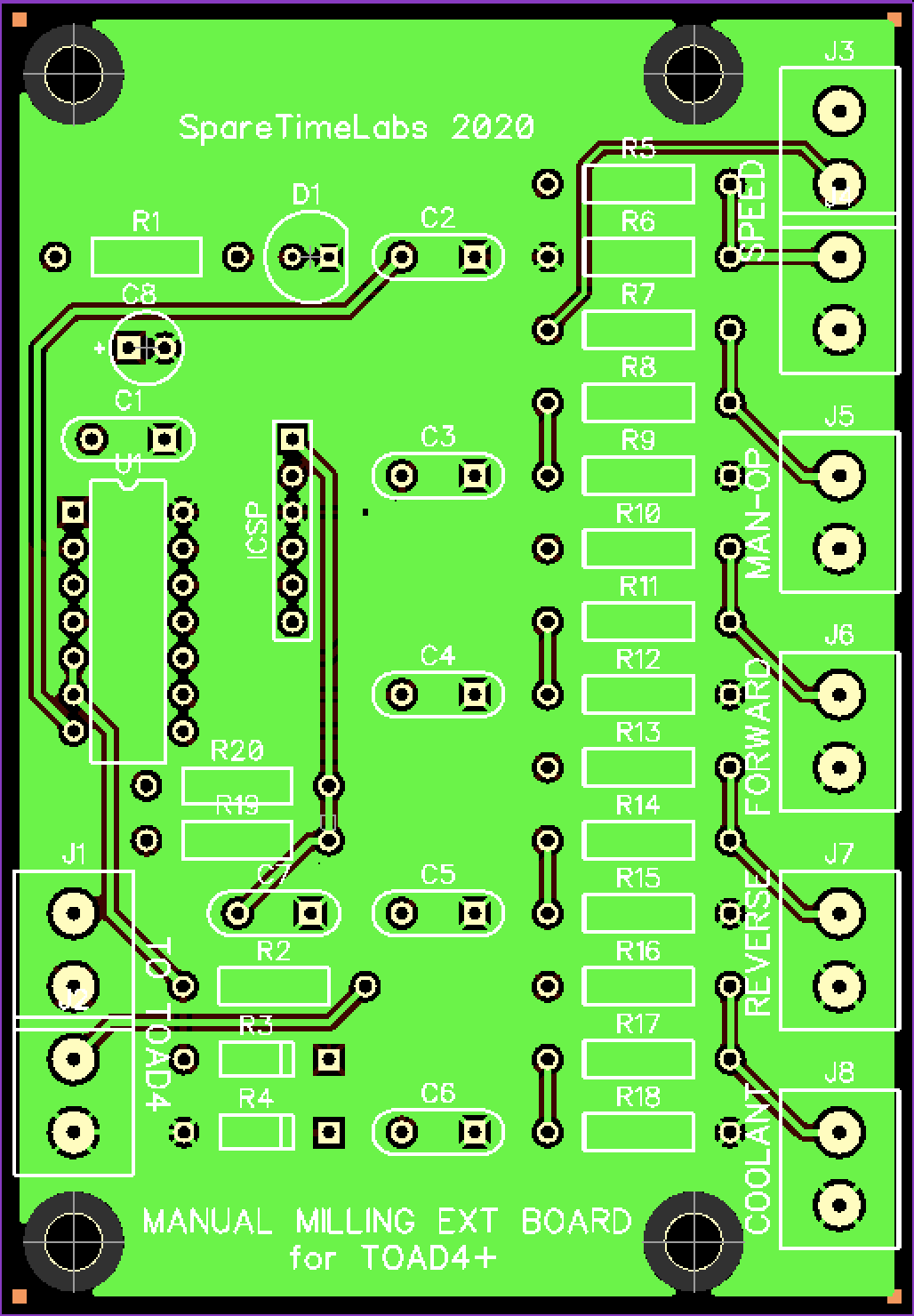
Building the board
There is nothing special about building the board. Start from the physically lowest components i.e. the resistors and work your way to the higher ones.I recommend using a good quality IC socket for the PIC16 processors in case it turns out to be necessary to modify the firmware. It is possible to update the firmware through the ICSP interface but that requires a PICKit3 programmer.
Speaking of the ICSP connector, that is superfluous if you do not intend to use it in which case the components R19,R20 and C7 are not really necessary too.
The screw terminal holes on the board are marginally tight so take care in selecting the actual screw terminal type so that it has thin enough pins. Do not drill through the holes to make them bigger as that will severe some of the connections.
Modying the TOAD4
You need to solder a 50 ohm resistor in parallel to the resistor R16 on the TOAD4 board. This is because otherwise the RC filter in that originally analog input is too slow. You need to upgrade the TOAD4 firwmare to version 2.0.9-4 which is available as part of EazyCNC 2.0.36.Wiring the board
The board is intended to be in the same enclosure as the TOAD4 board as it is basically just an IO extension board. However all the IO is protected so it may be possible to mount this board to a separate enclosure using a shielded cable. This however increases the risk of running into EMI problems.Note that the SPEED adn TOAD4 connectors or screw terminals are have four connections although only three positions are utilized. This is to allow the use of the same two pole terminal everywhere.
The board needs to be connected to the POTENTIOMETER INPUT connector J1 on the TOAD4 board. This connection should be relatively short but up to one meter should be fine because of the slow speed and the protective components.
All other wiring should be kept short, preferably in the order of 10-20 cm. This should not be a problem as the natural place for this board is next to the front panel of the enclosure that houses the manual control switches. In this way only three wires need to be run from this board to the TOAD4 board.
A linear potentiometer of 5 to 10 kOhms value mounted to the front panel of the manual control enclosure needs to be wired to the SPEED connector. Take care to wire it so that when the potentiometer is wound to extreme counter clockwise position the potentiometer sliding contact is nearest to the contact connected to the ground.
All the other inputs need to be wired to 'normally open maintained' type switches. The board logic is such that if a input is open circuit or not connected then the associated function is not activated.
Using the board
The TOAD4 needs to be powered up because it supplies power to this board, but the connection to the computer does not have to be (but can be) functioning.When the MAN-OP input is open circuit the LED on the board briefly blinks about once a second. If you active the MAN-OP switch then the LED turns to solid ON and the TOAD4 firmware starts to obey the FORWARD,REVERSE,COOLANT and SPEED inputs relaying those signals to the corresponding outputs of the TOAD4 board allowing you to control the spindle and coolant with the manual control switches.
If EazyCNC is running in MACH mode then the manual controls override any of the on-screen buttons and G-code commands as far as the spindle and coolant are concerned. This is intentional as it allows you to run your G-code while at the same time manually tune the spindle speed. The down side is that you will also have to manage the spindle on/off and coolant manually.
To make the connection between the manual control board and TOAD4 reliable the communication speed is slow and all the communication is double checked. The end result is that there is a delay of about 100 msec between any manual control input and the TOAD4 actually carrying out the action. This should not be an issue but maybe noticeable when you are adjusting the spindle speed.
That's all Folks!