
[ TOAD4 LPT ] 20.5.2020
TOAD4 LPT-version
As mentioned in my recent article EazyCNC ~ A Different Approach in Digital Machinist maganize I have created an LPT (Line Printer Terminal) port version of my TOAD4 design.
This was done to 'scratch my own itch' when I bought a previously loved Sieg X3 Mill which the previous owner had converted to CNC using Gecko Drive's G540 four axis stepper motor driver.
This LPT port board is even less of a product than the original TOAD4 board and not up to my own standards, though it works fine.
It was rather quickly created over some couple of days in December 2017, ordered on the 16th from AllPCB and amazingly it was deliverd to our doorsteps by DHL just before Christmas so I was able to take it with me and play with it over the holidays.
Since the articles publication there as has been more interest in that board than I ever anticipated. Fortunately I ordered a dozen boards or so back then which boards are now all but gone.
Because of the interest I'm considering if I should design a new TOAD4 LPT board that would support more I/O.
The purpose of this page is to support people who are building the LPT version
TOAD4 LPT versus TOAD4 versus Gecko G540
The TOAD4 LPT board supports all the features of Gecko G540 plus it has one extra input for probe.The board does not support coolant control nor driver enable signals. So with this board you cannot control a coolant pump nor can you disable the steppers for manual control of the axis.
Following is a table of the wiring of the TOAD4 signals versus the G540 DB25 connector pins.
If you are using the board as intended with the G540 then you really don't need to care about these, it should just work if you follow the wiring instructions in the G540 MANUAL
| TOAD4 | PIC | Gecko G540 | DB-25 |
| STEP_X | 19 | X-AXIS STEP | 2 |
| STEP_Y | 20 | Y-AXIS STEP | 4 |
| STEP_Z | 21 | Z-AXIS STEP | 6 |
| STEP_41 | 22 | A-AXIS STEP | 8 |
| DIR_X | 15 | X-AXIS DIRECTION | 3 |
| DIR_Y | 16 | Y-AXIS DIRECTION | 5 |
| DIR_Z | 17 | Z-AXIS DIRECTION | 7 |
| DIR_41 | 39 | A-AXIS DIRECTION | 9 |
| REF_X | 4 | INPUT 1 | 10 |
| REF_Y | 5 | INPUT 2 | 11 |
| REF_Z | 6 | INPUT 3 | 12 |
| REF_41 | 7 | INPUT 4 | 13 |
| SPINDLE_FWD | 8 | OUTPUT 1 | 17 |
| SPINDLE_REV | 9 | OUTPUT 2 | 1 |
| PWM | 36 | VFD PWM | 14 |
| PROBE2 | 3 | - | - |
(1) For historical reasons the A-axis signals in TOAD4 are named '_4' instead of the more appropriate '_A'.
(2) The probe input is available on the TOAD4 LPT 3 pin header J1 pin 2, see the schematics for details.
Building the TOAD4 LPT
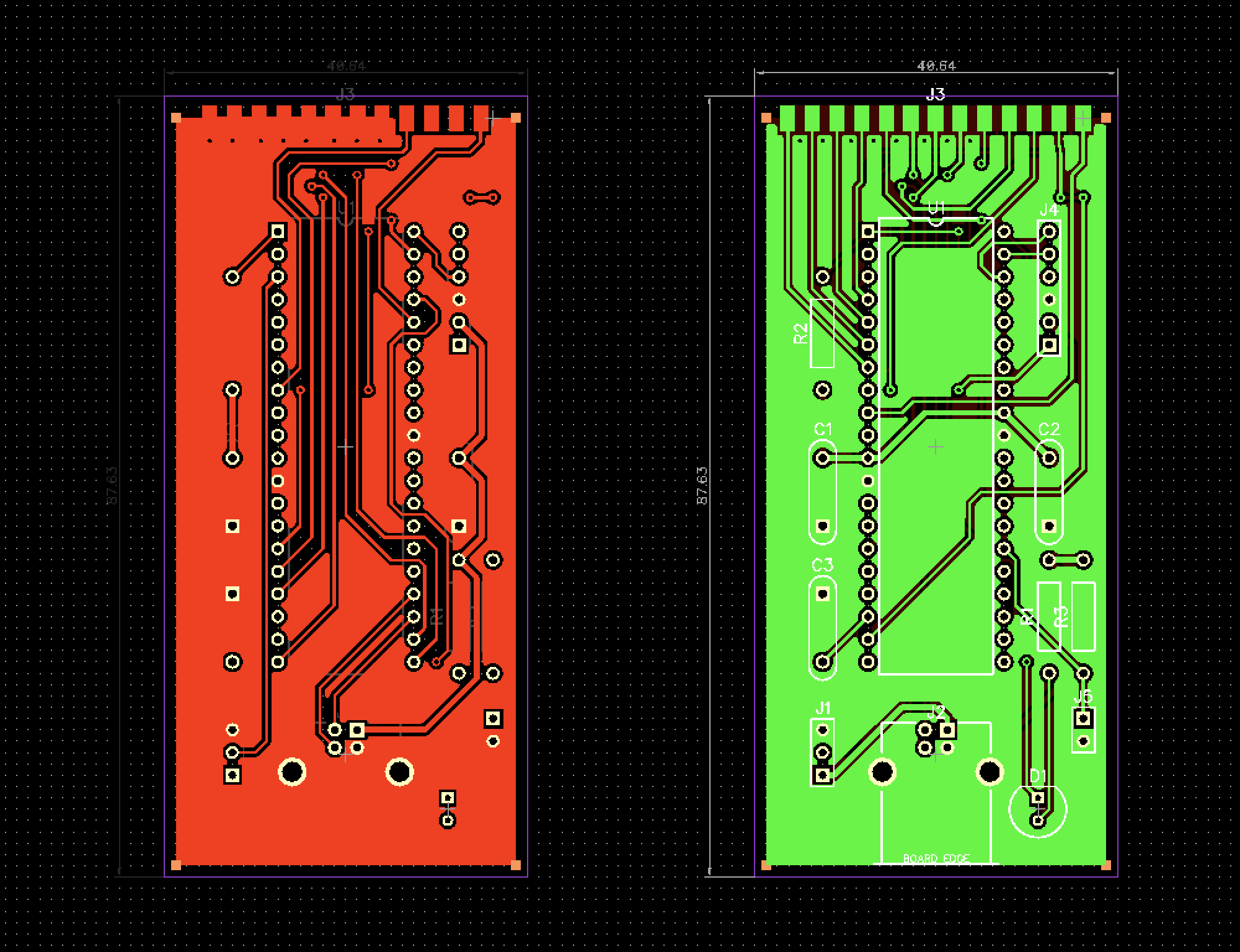
There is really not much to say about building the board, as you can see from these pictures:
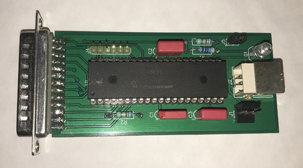
TOAD4 LPT Component side
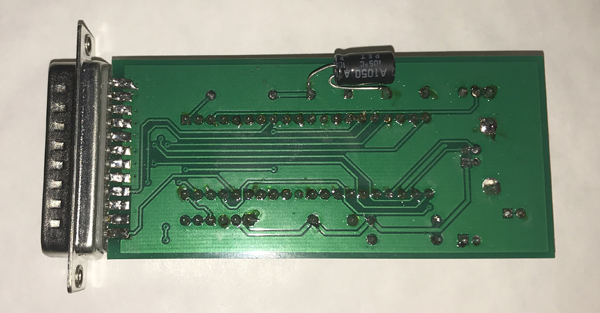
TOAD4 LPT Solder side
Starting with the lowest components usually makes assembly easiest.
Take care that LED, J1 and especially the DB-25 connector are soldered to right way.
Take care the U1 is soldered or inserted into a socket the right way.
The DB-25 connector is meant to be assembled so that the PCB is pushed between the rows of pins sot that upper row of 13 pins is on the componentn side of the PCB and the lower row of 12 pins is on the solder side of the PCB.
Note that the schematics and the PCB are missing a 10 µF (Cx) electronlytic capacitor which should be soldered onto the solder side of the PCB, as seen on the picture above. Mind the polarity and do not create short circuit between the +5 Volt and ground plane.
It is important to install the jumper block at J5 to prevent the PIC processor from entering the firmware update / bootloader mode. If that happens it may become necessary to update the firmware with EazyCNC Firmware Update function before the board can be used.
Schematics and PCB Layout
Below you'll find the schematics and PCB layout (click the pictures for larger versions).
Unfortunately the CAD software in which the schematics and board was design does not have a high quality .PDF output available.
For this reason it maybe best to view this data using the actual CAD sofrware, see resource section below.
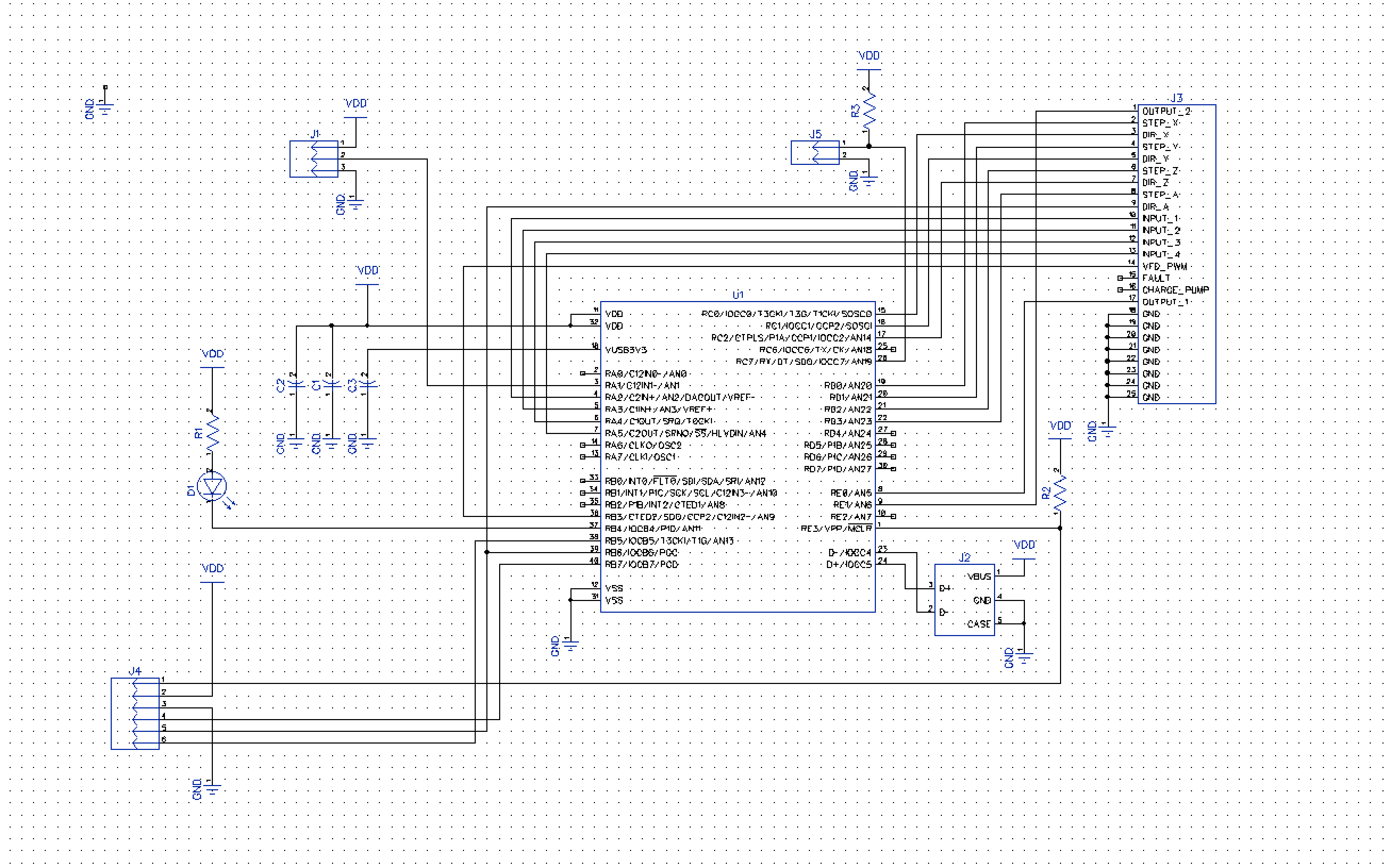
TOAD4 G540 LPT Schematics
TOAD4 G540 LPT PCB Layout
Parts List
| Component | Value | Note |
| U1 | PIC18F45K50 | Pre-programmed (do not use PICKit2/PICKit3 to program) |
| D1 | LED 5 mm | Elf and Safety regulations require the use of green LED |
| J1 | 3 pin header | for PROBE, NOT optically isolated |
| J2 | USB 2.0 B Jack | ensure compatibility with PCB layout |
| J3 | DB-25 male | with pins that suite the soldering method |
| J4 | 6 pin header | Not used (for ICSP PICKit style) |
| J5 | 2 pin header | Install a jumper block before powering up |
| R1 | 220 Ohm | 1/4 Watt |
| R2,R3 | 6.8 kOhm | 1/4 Watt |
| C1,C2 | 100 nF | ceramic bypass |
| C3 | 330 nF | ceramic bypass |
| Cx | 10 µF | electrolytic > 10 Volt |
First Test
The board should immediately power up as soon as the USB cable is connected to the board and a computer.The LED should start blinking.
A slow blinking means that the PIC is alive and waiting for the OS (Operating System) in the computer to configure this (TOAD4) device.
A fast blinking means that the OS has recognized and configure the device and associated it with the HID driver and the device is ready to work.
A steady ON state on the LED indicates that the device is in bootloader mode. If that happens unplug the USB connection, insert the jumper block J5 and re-plug the USB connection. If that does not help, you need to update the firmware as described in the EazyCNC User Manual.
Resources
The schematics and board were designed in a PCB CAD software called DipTraceSince this is no business I felt it was okey to use their Freeware version which is available from here .
You can use that software to view and modify the board design files should you need to do that.
To allow you to do that I've made all the source files as well as the final Gerber files available below.
From the Gerber files you should be able to produce your own boards if you so want.That's all Folks!